CBT36 Speaker Build

A background on this speaker design

This kit was sold from Parts Express up until about 2016. Parts Express still sells the driver components, but the cabinets and kit are no longer available. 

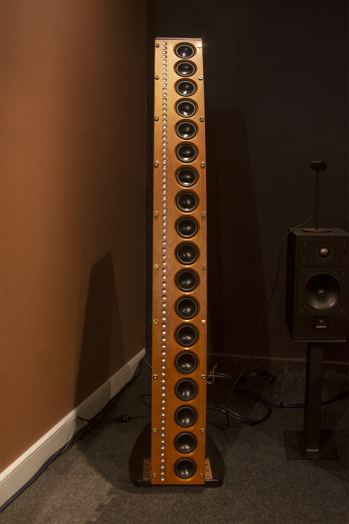
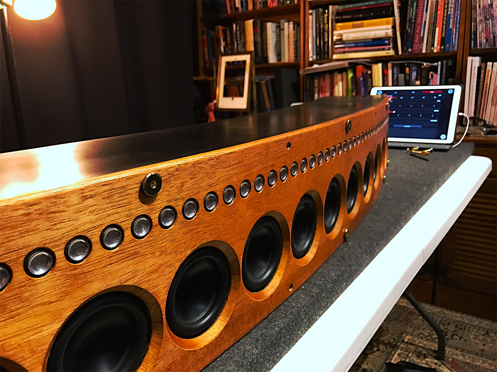
    The CBT36 speaker is named for the type of acoustic output (constant beamwidth transducer) and the number of full range drivers in the array (18 for each channel). The video series by the designer of the speaker, Don B. Keele, goes into great detail about the purpose of the speaker’s design. This is how I became fascinated with the technology behind it. After reading reviews and written material presented on this type of line array I became convinced this was a superior design to more traditional speakers, which produce sound waves that radiate out into a room from single sources for low, mid range, and high frequency sounds.  That can often produce an inconsistent listening experience when moving around the room. The CBT36 eliminates a lot of these issues through a shaded array. The curvature of the speaker is an integral part of this shading, and not just an aesthetic choice. I’m not an audio engineer, but can appreciate the benefits of good design as it relates to practical results. When the design also looks visually pleasing, it’s a bonus! There is plenty to read about this design since it has been around for about five years, and Parts Express is a good starting point. Here are a few shots of the finished left channel.  I’ll explain my build and finishing process in the following sections.

    Inventory and testing

    The CBT36 cabinets are shipped in three boxes. Two contain the MDF cabinets. The third contains the drivers, electronics, hardware, and manual. The manual is a 80+ page book of instructions with lots of images that accompany step-by-step instructions. My kind of manual! The first thing the manual tells people to do is an inventory check. There are hundreds of components (screws, wires, resistors, circuitry, and speaker drivers) to inventory and check.

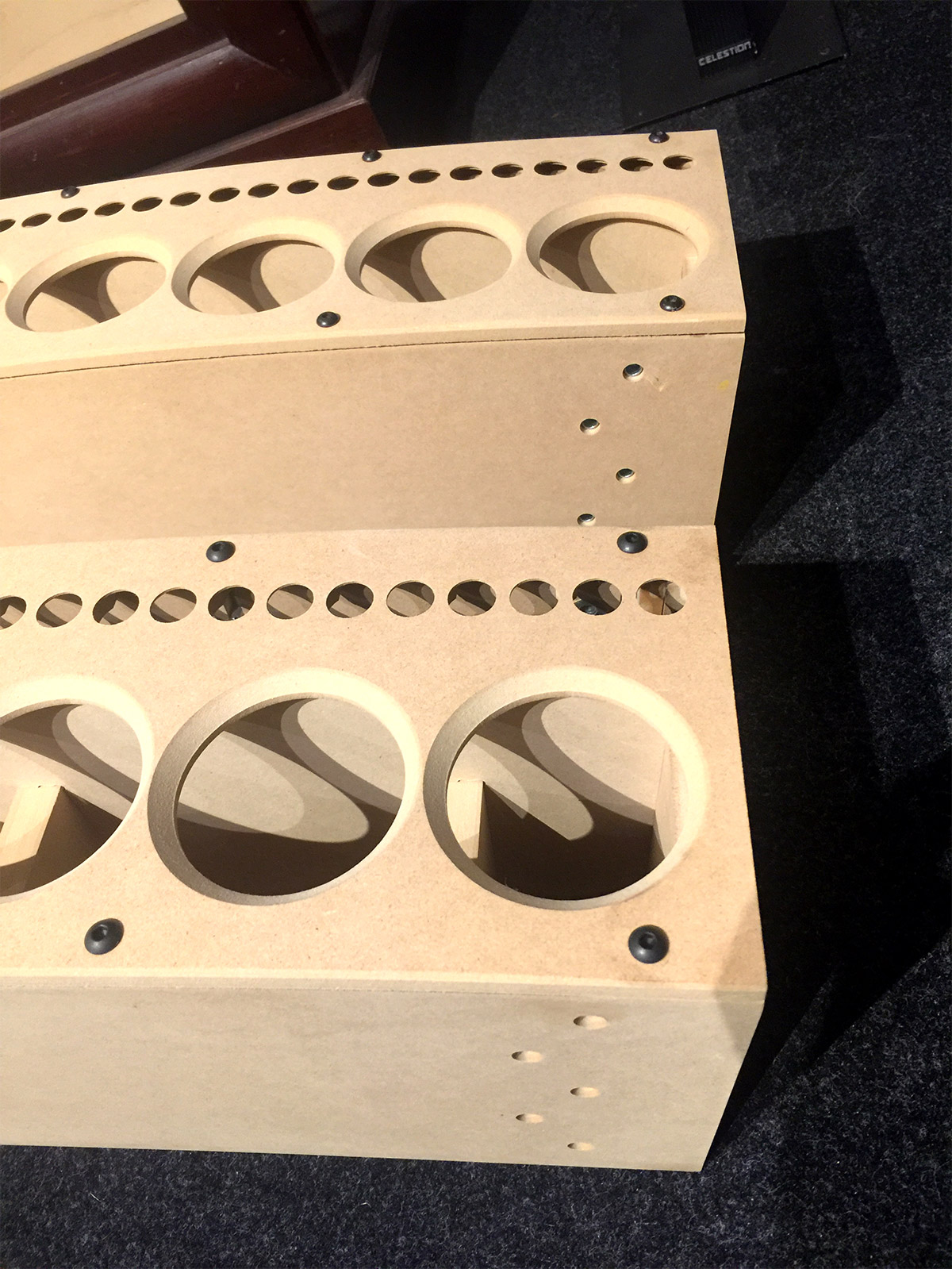
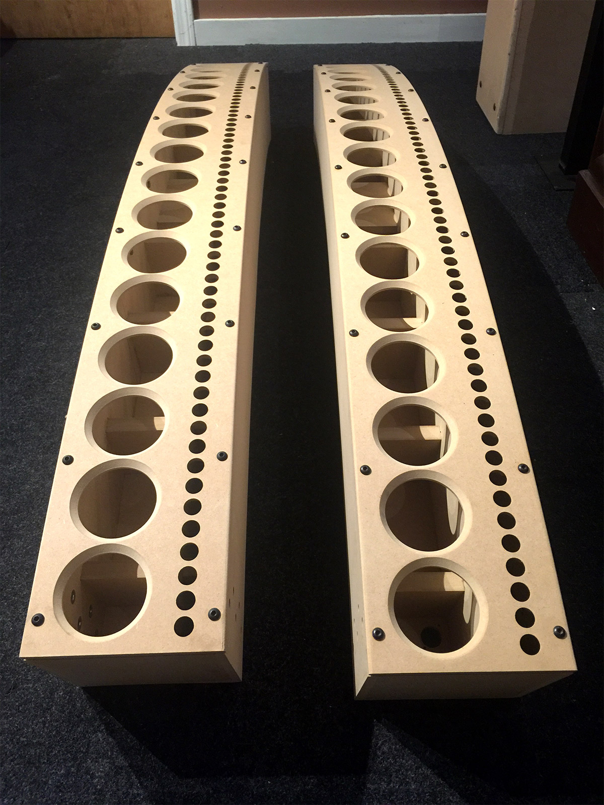
    Some of the components require testing, and this is the first step taken since replacement parts take time to ship. Testing everything is absolutely critical to a successful build. I ran into a few issues with some of the speaker drivers and had to get replacements for two full range drivers and a tweeter array. Additionally, I had to send the cabinets back. The manual tells people not to throw away the shipping boxes just in case this happens. See if you can spot the reason why I rejected these cabinets.

    Veneering the front panels

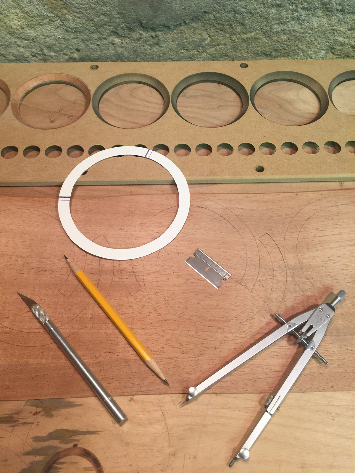
    There are way too many steps in the build process to cover is a single post, so I am focusing primarily on the customization of the front panels. Some previous builders describe taking the panels to an auto body shop where they can be primed and coated with a glossy finish in a spray booth. That was not for me. I wanted the speakers to look like a piece of vintage furniture. I started with veneering the inner bevels for the main driver holes by producing a card template for cutting individual pieces from a thin sheet of adhesive mahogany veneer. No additional prep was needed for the front panels.

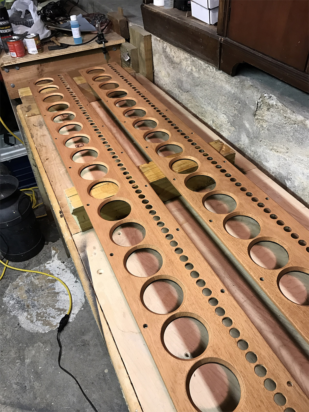
    Here is a shot of a few of the cutouts and how I positioned them with the wood grain following the midpoint of each curve. I did this in anticipation of how the veneer would get trimmed in relation to the grain running down the face of the panels. I wanted a contrasting pattern that spread the light out differently on the beveled veneer.

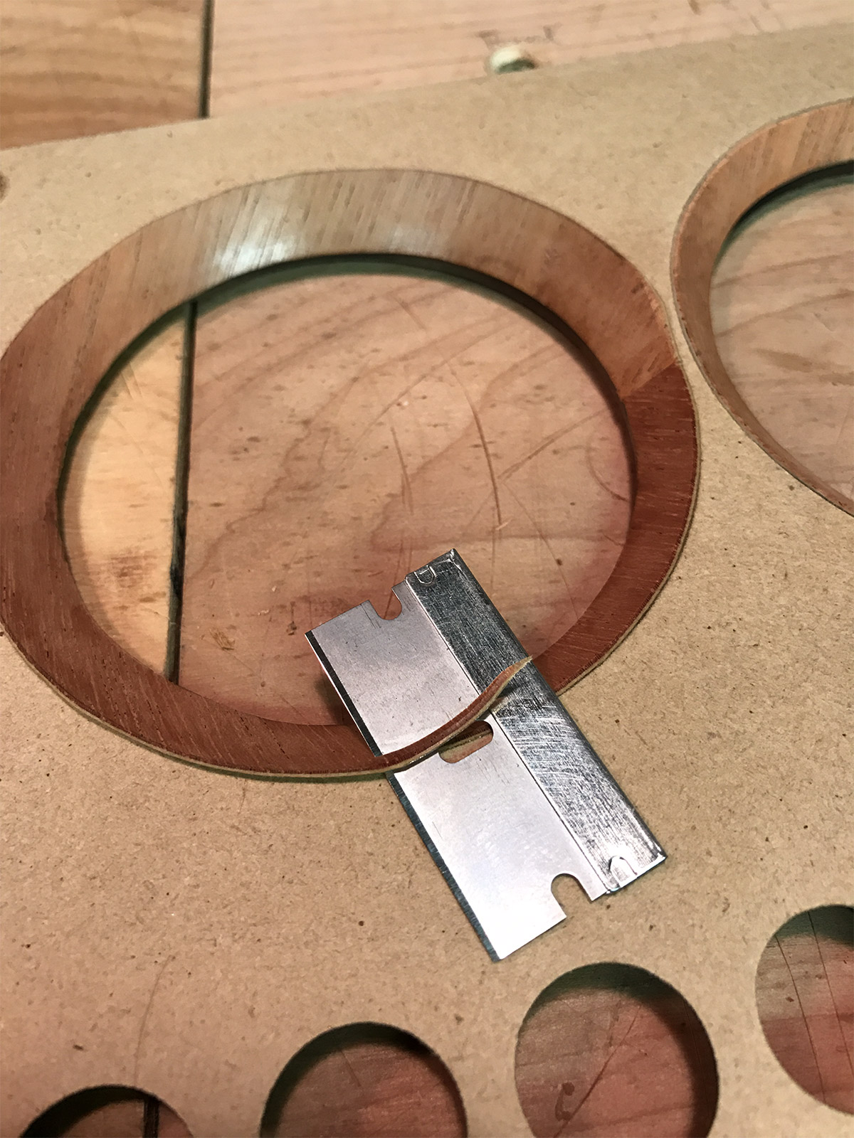
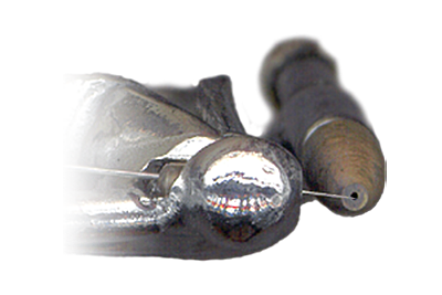
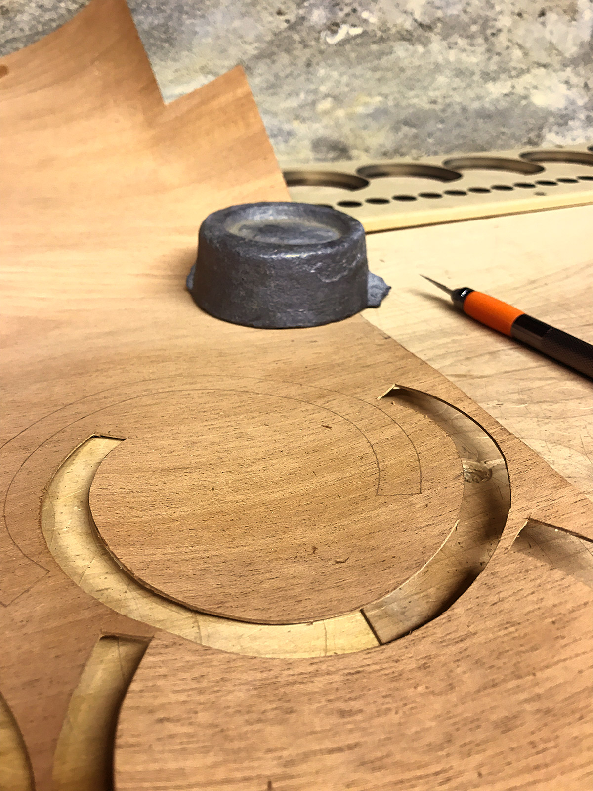
    Here are some trimmed pieces of the veneer applied to the bevel in the panel. I did this with a soldering iron as a heat source and burnisher to fasten them really well before trimming. Then, I used a single edge razor blade as a trimming tool. The image shows the start of the trimming process on the top part of the bevel.  I also trimmed The lower section of the bevel in the same fashion. one of the finished bevels can be seen in the upper right of the image.

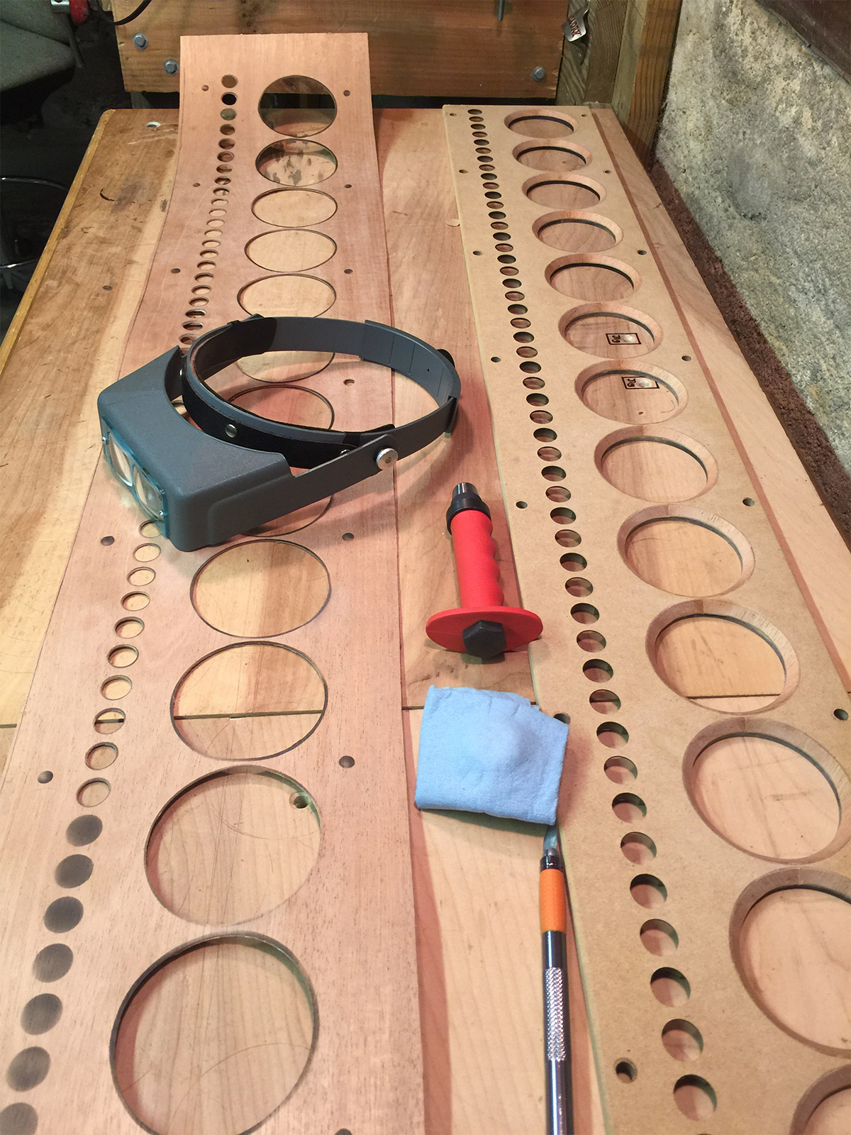
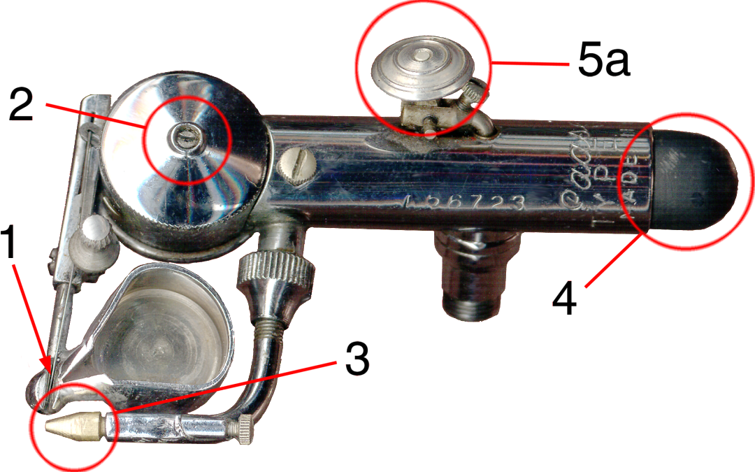
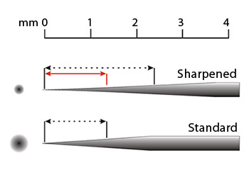
    Prior to veneering the inner beveling of the main driver holes, I prepared longer sheets of the mahogany veneer by using an airbrush to spray markings for each cutout in the veneer. This image shows the final stage in the process of cutting. I used an Exacto knive for the larger holes and a leather punch for the smaller holes. The Optivisor helped me maintain the precision needed for the hand cutting process and positioning of the leather punch. Each cut left room for material to be removed after application.

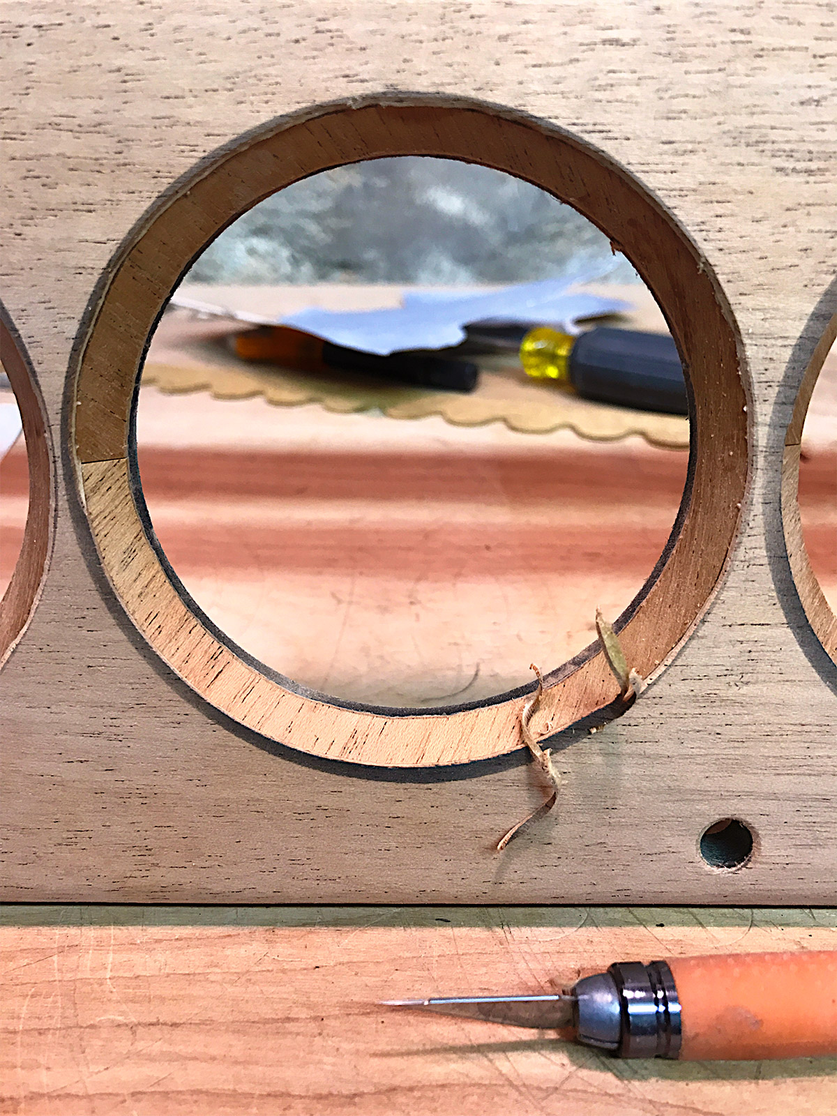
    With all rough cutting completed the front veneer is carefully positioned so that all the edges overlap each hole with additional veneer ready for precision trimming. I used a domestic iron to heat cure the veneer to the MDF, folding the edge of the veneer around the the camphor edges of the panel. Then I used an Exacto blade to do the final precision trimming.

    Here I am using a rotary grinding bit to speed up the trimming process on the tweeter holes. There are 72 of these holes on each panel, so the grinder was essential for keeping the time spent on each hole down to about 5 minutes. Careful attention was taken not to enlarge the holes any more than the original MDF, which is about as thick as the vener in these areas.

    The final stage in the veneering process was lots hand sanding! I used sanding blocks for the flat sections starting with 320 grit paper, working up to 600 grit. The beveled holes and tweeter holes required the same attention with small hand held sanding strips.

    The trimming, application, and sanding process was repeated on the second panel, then I prepped both panels for a light stain with Minwax Pre-Stain and Minwax Old Maple to bring out the grain and the deeper reds in the mahogany. After a 24 hour drying stage I spent another 10 hours sanding to a polished finish with 1200 grit sand paper, then applying carnauba wax to seal the finish.  The whole process took close to 150 hours.

    Assembly

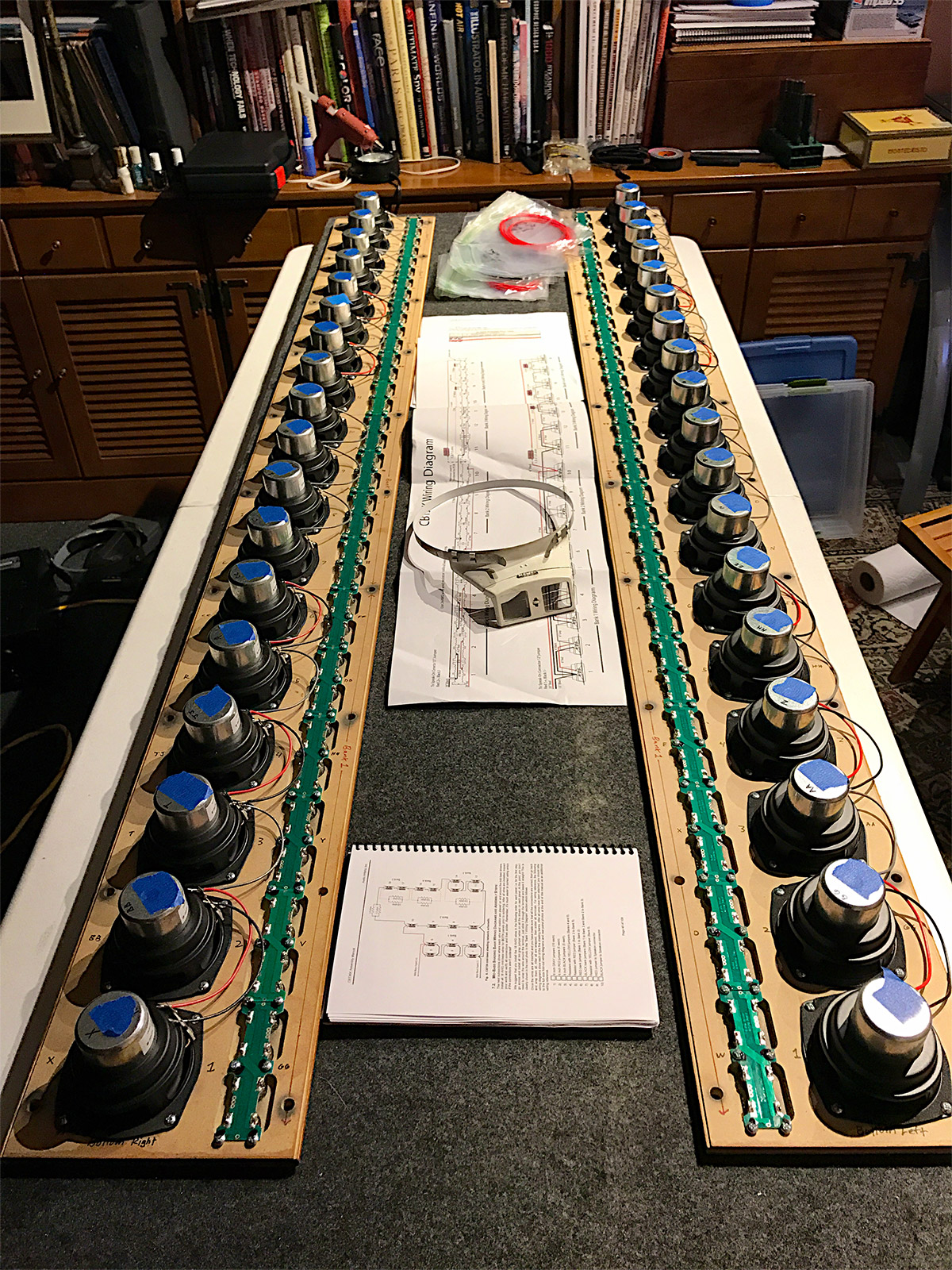
    Here are the front panels flipped over on a felt lined workstation to protect the finish while mounting the drivers. I have just begun the wiring process at this stage. Most of the electronics assembly is covered in the manual, so I will just focus on some of the areas I deviated from the instructions to customize the look of the speakers, and enhance the build.

    The manual had suggested mounting all the resistors with a hot glue gun, but I opted for a technique I read in the forums using zip ties. I also applied acoustic foam between each resistor and the mount to eliminate the possibility of any component causing vibration inside the cabinet.

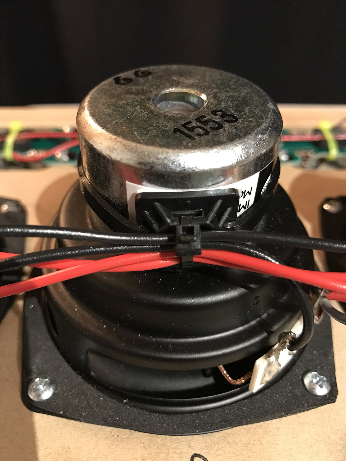
    I used the same technique to fasten bundles of wires down the length of the array for both the full range drivers and the tweeters.

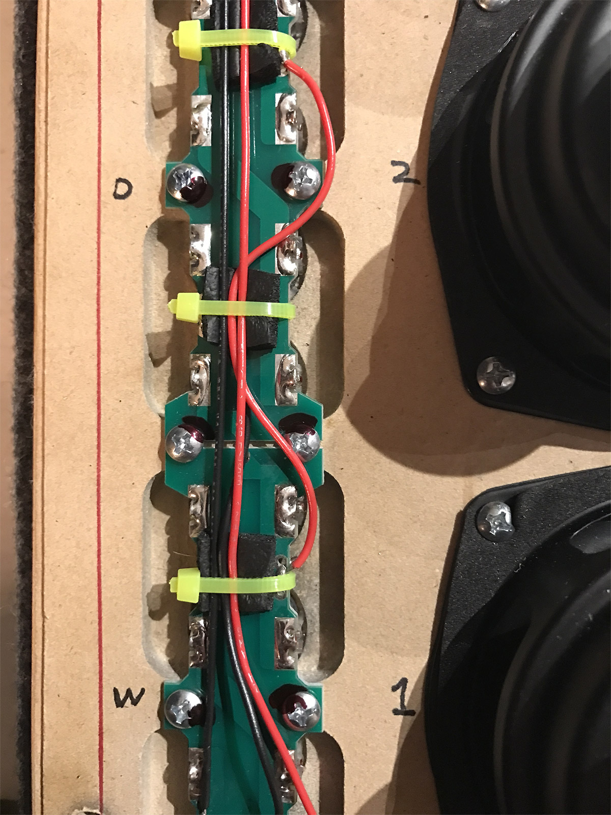
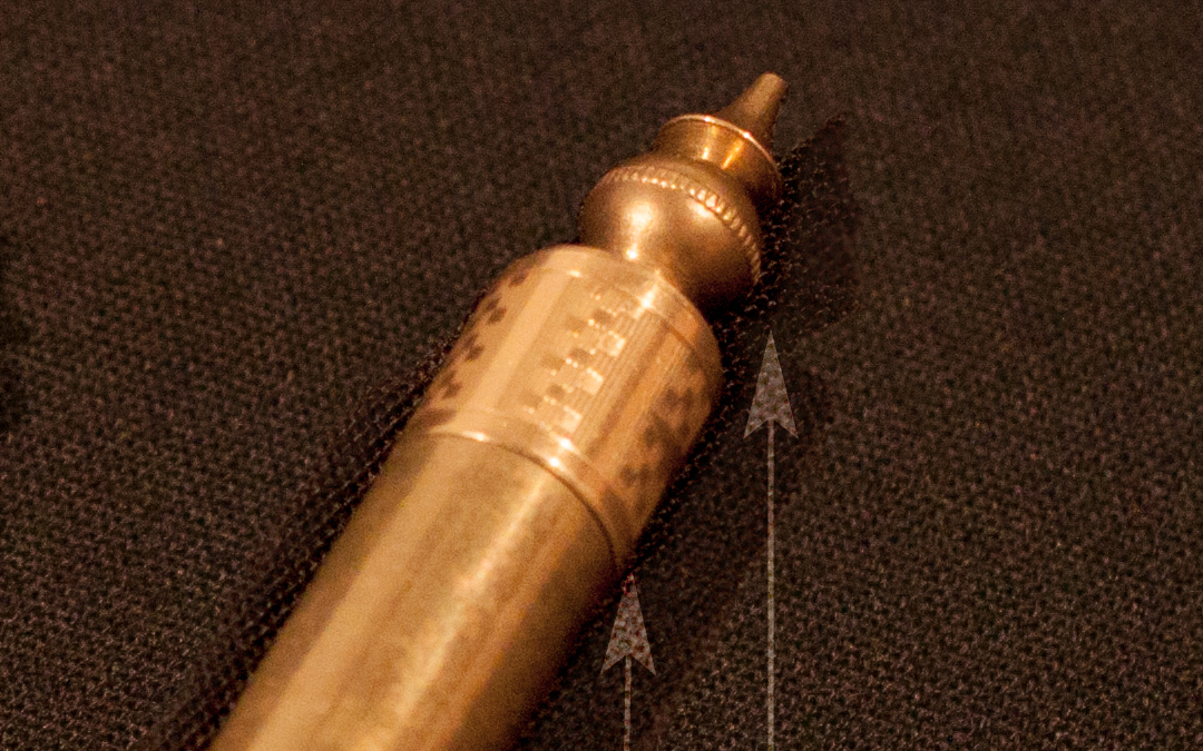
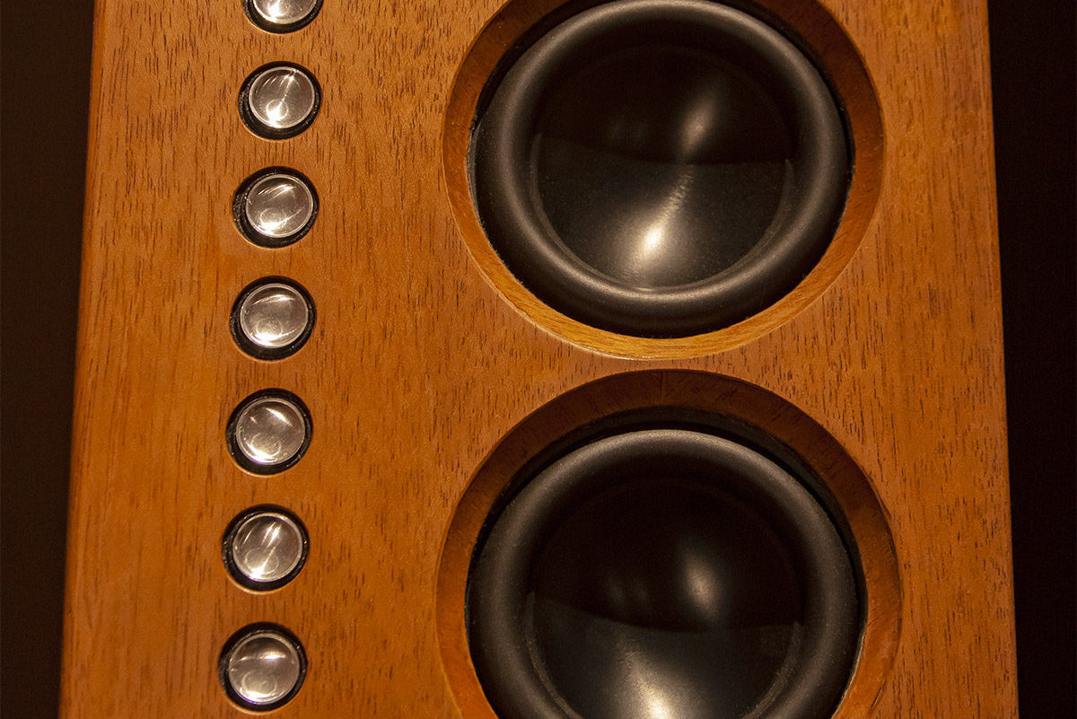
    The same wire fastening technique is seen here. Tweeter arrays come attached to circuit boards with four tweeters per board. The boards are screwed into place and connected with jumpers and wires depending upon how the banks are shaded (see the manual for a complete description). The numbers on the panel mark positions for each set of drivers. Before mounting the drivers I tested and ranked the impedance of each one, placing speakers with a slightly lower impedance towards the top end of the speaker panel.

    Here is the right panel fully wired for testing. I did testing twice since there is no margin for error once the wires and circuits are soldered into place. The first test confirmed all the drivers worked, and that the shading was correct. The second test confirmed the same results with the soldering complete.

    This is the left panel undergoing the same testing prior to sealing the cabinets with a set of 20 wide flange brass bolts. The bolts are not part of the original parts list. I like the look of them better than the black ones that came with the kit. I opened and shut the cabinets a few times, which is why only some bolts are fastened in these images. The bolts have compressible rubber washers to seal the cabinet and protect the front panel.

    Steampunk Wacom, Part 1 (The Stylus)

    Steampunk Wacom, Part 1 (The Stylus)

    The inspiration for this Steampunk Wacom stylus (and soon to be completed tablet, Part 2) was born out of two events that coincided a few years ago. One was the fact that every so often I need to upgrade my equipment to support new software and features. The other was a chance find of an antique lap desk at the local swap shop (technically, the dump) around the time my Intuos 2 became a dust gatherer. I hate getting rid of graphics stuff like this so “What to do with it?” was top of mind.

    A lap desk is a throwback to a Victorian era travel necessity for any well connected globe trotter that needs to keep up with correspondence. Perhaps a lap desk could be considered the laptop of the 1800’s. It certainly makes sense based on name and function. The surface layout of a Wacom tablet (especially an Intuos 2) is remarkably similar to the divide between the richly veneered wood and felt on the business surface of a lap desk. There are also cool compartments that come along with a lap desk design that can serve as storage space for a stylus and those tiny tips that I keep losing. Although in disrepair, I didn’t want to cannibalize the lap desk for parts since it was nearly intact and a little on the small side. Instead I began a slow and methodical process of selectively collecting objects and materials I could use and re-manufacture into like components, all from recycled parts of course!


    Original Intuos 2 Stylus

    Original Intuos 2 Stylus

    I worked first on the stylus (unmodified original shown on the left) knowing that this would be the most intricate work. Must-have materials in any good Steampunk creation are always brass, wood, and leather.  This led me to work out a design for the stylus based off of airbrush, fountain pen, and clock parts which I had lying around. The stylus has three controls other than the tip. The rocking button in the middle of the stylus looks like a single slim button, but once one gets into the guts of the stylus it is clear that the button design triggers two independent toggles on the internal circuit board. The third control is the digital eraser on the back end of the stylus.


    Trigger assembly close-up

    A rocking motion is an ideal movement for dual trigger mechanisms found on most airbrushes which is why I chose to modifiy the rocking button assembly by mounting a trigger from an old Passche airbrush on top of it. See my Custom AB post for comparison with the image above. This actually works better for me since the trigger puts my finger in a more relaxed position above the stylus, and I don’t have to move my finger to opposite ends of a button bar to toggle the two controls. Instead I just use the trigger’s rocking motion the same way I would control paint flow on an airbrush. Coincidentally I also happen to own an airbrush version of the Wacom stylus which is even more awkward to use than a traditional button stylus. I was always baffled by Wacom’s choice of a hybrid mouse wheel over a traditional airbrush trigger on that device. Wacom built pressure sensitivity into the stylus tip. Why not do the same for virtual paint flow on a trigger?


    Tip assembly close

    I chose 1/2 inch brass tubing for the stylus body and discovered early on that any type of metal at the front of the stylus interferes with the signal reception at the tip. I changed my design as a result of this, and decided to modify and cover the existing stylus body with non metallic materials. In this case, I used a strip of leather from an old wallet interior applied with a strong cyanoacrylate adhesive, and behind that, permanent black ink from an overhead projection marker to mask the original color of the light gray body. I was able to get away with a gilding process at the tip using 24 carat gold leaf probably because its such a thin metal. The important thing is that it works! The assembly required precise cutting of the stylus body, leather, and brass tubing, plus the manufacture of a small brass strip to cover the rocking button.


    Finial assembly close

    At the opposite end of the stylus I sacrificed the eraser functionality for a bit of decorative metallic flair. I never got used to flipping my stylus around like a pencil when I could instantly toggle the eraser by moving the function to the back toggle on the trigger. The finial at the end of the stylus is a decorative gold plated band from an old 1930’s fountain pen and a finial from a Schatz German table clock. Those parts were merged together with a few threaded brass parts I had laying around (not sure where they came from) and some foil tape typically used for masking photo slides. The foil tape was used to help non-threaded parts like the pen ring fit snugly over the other brass parts. This one detail makes the design LOOK Victorian.

    Stay tuned for Part 2 of this post, where I will discuss the process I went through in finding and assembling recycled parts for the tablet’s body.

    How to Produce Invisible Digital Watermarking in Photoshop Without a Plug-in

    How to Produce Invisible Digital Watermarking in Photoshop Without a Plug-in

    Where is the watermark?

    Digital watermarking is often seen as a light but visible mark within an image, and can include a logo or URL to show copyright ownership. It is there for everyone to see (and remove). Invisible watermarks take this concept a step further and make the watermark less obvious and harder to remove. Digimarc is an invisible watermarking filter for Photoshop and is automatically included as a default. It is supported by a third party, Digimarc, and requires a subscription to take full advantage of it’s features. Its purpose is to embed an invisible watermark into an image to protect against copyright infringement and track the use of the image on the web. Digimarc works on two fronts. It embeds an invisible (strong) watermark into an image by encoding information (Author name and creation date) into a noise tolerant image’s least significant bits. That information is also stored in a database and can be cross-referenced against other copies of the same image all over the web. If an unauthorized use is discovered, the original author can prove who they are beyond any reasonable doubt and call out the infringing party.

    I had a problem with copyright infringement of my own and thought Digimarc might be a perfect solution, but discovered that Digimarc’s service would not access the virtual world server where my texture images were stored. This roadblock inspired me to come up with my own type of invisible watermark using Photoshop to regain control over both the stored data, storage method, and file format. It is also important to note that the Digimarc filter can still be used to embed a second watermark into the same image if needed for distribution on the web.

    Here are the steps I use for invisible digital watermarking in Photoshop:

    1. Give the original image a New Channel for encoding information. This converts it to a carrier file.
    2. Generate a second black and white image of the same dimensions and place multiple copies of a QR code in it. This is the information file which can carry contact information, a URL, or any message.
    3. Run a Gaussian Blur on the QR code to soften the edges so it will blend well with the carrier file image. Test this with a code scanner, then Copy and Paste it into the New Channel in the carrier file.
    4. Select part of the carrier image using the newly created Alpha Channel, Copy, then Paste it as a New Layer. This produces a second layer with only the coded portion of the image. It should be completely invisible at this point.
    5. To embed the code as imperceptibly as possible, run a Hue Saturation adjustment (altering the image hue by no more than five steps) and add 3% noise into the image with a noise filter. More alterations can be added if needed, but the general idea is to cover the coded layer with noise that uniformly alters the pixels slightly through all colors and shades.
    6. If the effect is too harsh the Opacity of the layer can be reduced to make the effects more subtle.
    7. Copy Merged, Paste the coded image into a New File, Flatten it and Save it to any popular file format (JPEG, PNG, Targa)
    8. Calculate the Difference between the original master file and the encoded file, Copy Merged, Paste into a New Layer. Run an Equalize adjustment on that layer to reveal the code again.
    9. To make the code readable under higher compressions, copy and compress the master file, then repeat steps 7-8.

    This steganographic method may not be as sophisticated as Digimarc’s, but works for my application needs and gives a stealthy tracking mechanism for policing my work on a virtual world server hosting lossless JPEG 2000 file formats. It also survives moderate resizing, cropping, and compression. Best of all, it can be done entirely within Photoshop’s tool set without need of a third party add-on or a subscription.

    Cat image
    Coded cat image
    Raw extracted code
    Enhanced code

    rossmanart.com Receives an Upgrade

    rossmanart.com Receives an Upgrade

    The old rossmanart.com has a new face on the web. The URL is the same, but new content is better integrated with the major social tools we all use, as evidenced by this post (published @ rossmanart.com and distributed to various social platforms through WordPress). This upgrade will allow Rossman Art to easily reach out to and build upon an existing audience without the added burden of maintaining and propagating  isolated content. Credit for the back-end development goes to Elegant Themes for their Divi theme using the WordPress content management system. The major portion of the site still remains a portfolio showcase, but new sections have been added for a Blog and custom curated Newsletter (through paper.li). I visit this newsletter daily to keep up on the latest trends in science, technology, and art. The site is open to subscribers, so anyone can can join to receive updates whenever new content is posted. Those interested in contributing content can contact Rossman Art and ask to have their subscriber status upgraded to Contributor, or Author.

    I hope everyone enjoys the new and responsive look of the site!

    Best,

    Jeff Rossman

    Customized Paasche AB Turbo

    Customized Paasche AB Turbo

    An Overview of the Customized Parts on My Paasche AB:

    This is an old how-to I resurrected from two previous generations of rossmanart.com. It’s been informative to people in the past, and also explains a bit how I use this device.

    PeelerPatNo-256852-Pg1For those unfamiliar with turbine driven airbrushes, it all started over a century ago in 1879 with an invention by Abner Peeler called the Paint Distributor. This was a system that delivered paint into an airstream on the end of a reciprocating needle. Others developed Peeler’s original design into the lighter and smaller instrument seen here. Thanks to Jens Paasche, the modern AB made its debut in 1904, and little has changed with the version still produced today. Most airbrush designs opt for a simple linear mixing of paint and air, but a modern AB remains true to the original design of Peeler’s, and has few rivals when it comes to finely controlled paint dispersal. This is a testament to the genius of the AB’s design.


    Costomized Turbo_top_In_Hand


    A normal AB has better control over paint flow than most other airbrushes, so why mess with it?*

    The AB’s only flaw is its temperamental behavior due to the complexity of its moving parts. This is the reason I chose to modify my own AB. The three main controls , trigger, speed regulator, and stipple adjuster all need regular fine tuning to maintain top performance. Simply put, I wanted finer tuning and better performance, and was going to do whatever it took to get it. I started by making small changes to some of these control variables to fit the AB to my illustrative technique. The first thing that I changed was the long red stock AB handle. I replaced it with a much shorter rubber insert (an eye dropper bulb) seen at #4. Holding the AB this way felt more natural to me. Other modifications followed. Hopefully this tacit knowledge will inspire other AB users with a wish to tinker.

    Customized_Turbo_top

    Customization Overview*

    Here is a general overview of the five areas of my AB that I have customized for comfort and better performance . (1) A Sharpened needle tip to take advantage of the trigger’s precision control. (2) A Low profile grease cup screw (not shown) for comfort. (3) Custom blast jet to narrow the air blast for better performance with a sharper needle. (4) Shortened handle for comfort and easier handling. (5) Dual trigger assemblies: The short one, shown here for comparison. The longer one allows for finer needle control.

    Customized_Turbo_extended

    The Trigger Assembly*

    I use this extended trigger assembly for better control when moving the needle in front of the blast jet. With a longer lever the thumb/finger must travel a greater distance to move the needle. This simple change is a borrowed trigger assembly from another Paasche V airbrush. It is very easy to switch between this and the original short trigger by tightening each assembly by hand. This allows for easy loosening and doesn’t strip the delicate brass threads. I rarely use the short trigger any more, so this one stays put.

    Customized_Turbo_top_close

    Needle & Customized Blast Jet*

    The combination of a smaller blast hole and sharpened needle is key to my AB’s performance enhancement. These two changes alone will significantly enhance a factory model AB. They are examples of what I term “the Maker mindset” – a DIY way of using existing tools to make better tools. My custom blast jet produces a stream of air about half the diameter of the factory supplied blast jet. I made it from a .125″ solid brass rod using a jewelers motor, sharpening stone, and micro drill bits. A tighter spray diameter coupled with a sharper needle produces a very thin line. The airbrush needle needs perfect alignment with the front of the blast hole for this to work. Also, I run the air pressure slightly higher than the recommended 25-35 PSI, but no more than 50 PSI to compensate for the narrower blast.

    Customized_Turbo_front


    Front view of the customized blast jet*

    This angle shows the sharpened needle extended in front of the custom blast jet. There is a narrow window of tolerance where the needle performs best in front of the blast jet. This is all fine tuned by adjusting the needle bend & sharpness, needle bearing, and angle of the paint cup. As long as there is little impact to the airbrush or damage to the needle or walking arm, these adjustments only need setting once until the needle needs replacement.

    Customized_Turbo_needle_compare

    Sharpening a needle*

    The taper on an original needle lengthens by sharpening its tip. This allows for greater control of the spray diameter over a greater distance of needle travel. This graphic shows the difference in a hairline spray diameter between a standard needle and a sharpened one. The red arrows indicate the area of increased performance. The dotted black arrows indicate the effective spray area along the needle. I use a sharpening stone with a jewelers motor to sharpen my needles. However, 1500-2000 grit sand paper also works well. I use this kind of sand paper often to polish and remove dried paint from my needles. This sharpening technique is also documented in “The Complete Manual of Airbrushing” by Peter Owen & Jane Rollason (now out of print, but available through Amazon). I highly recommend getting it if you own an AB.


    Disclaimer:

    Document icon*DO NOT modify your Paasche AB airbrush as described above if you don’t have experience maintaining it! Always consult the official AB instruction manual and parts list before attempting any adjustment or alteration to your AB!