CBT36 Speaker Build
A background on this speaker design
This kit was sold from Parts Express up until about 2016. Parts Express still sells the driver components, but the cabinets and kit are no longer available.
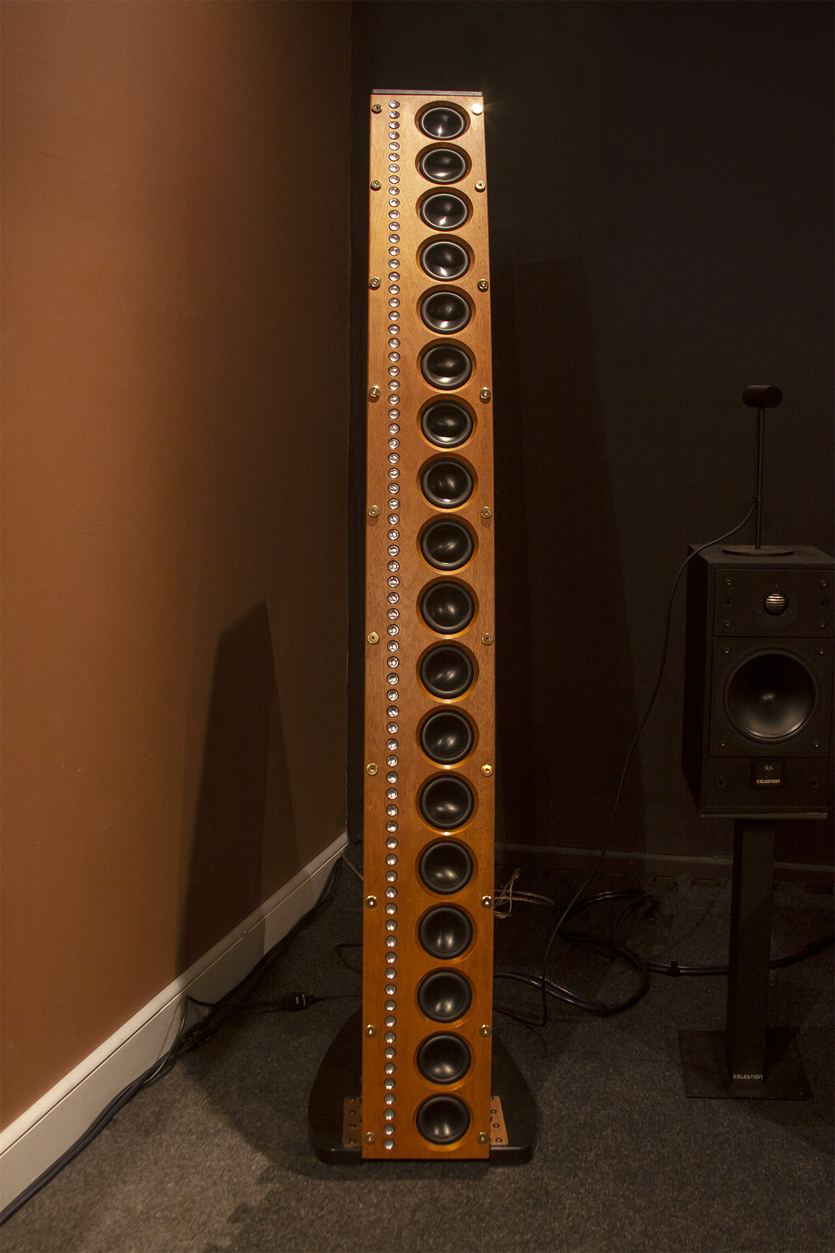
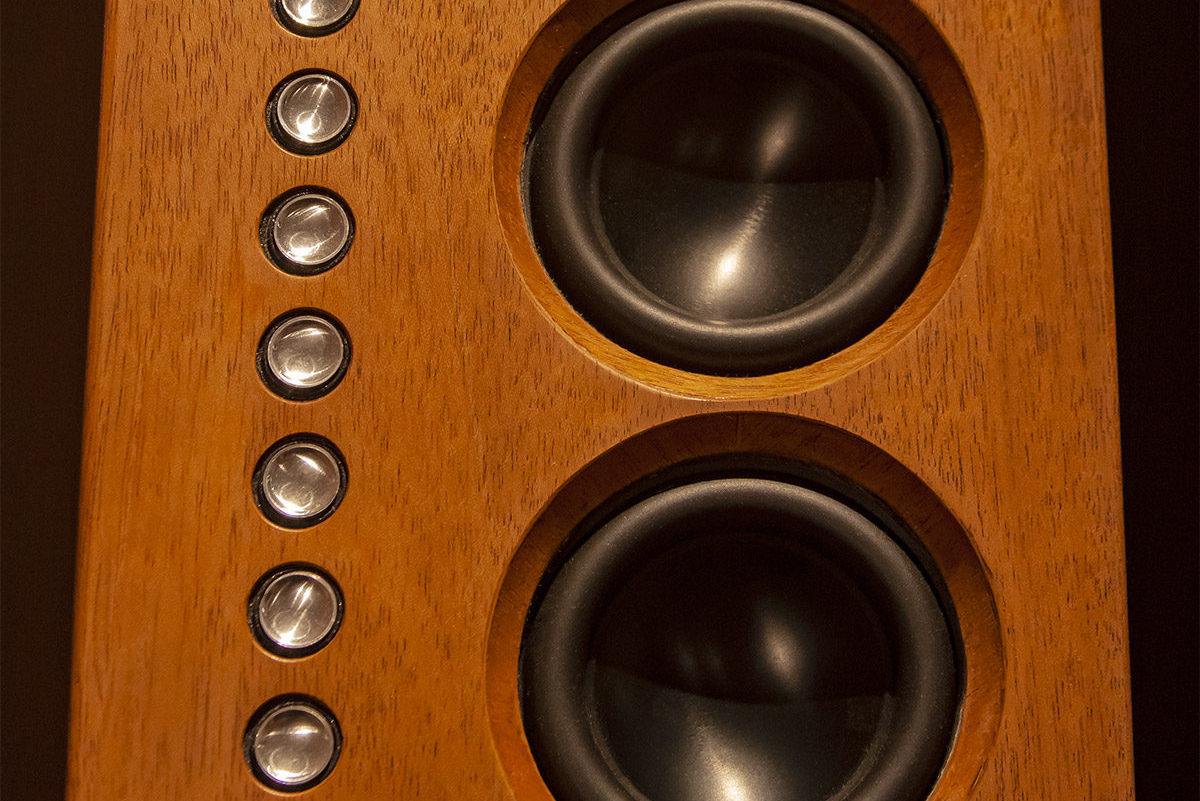
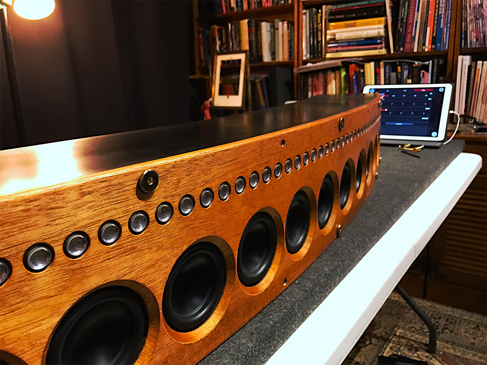
The CBT36 speaker is named for the type of acoustic output (constant beamwidth transducer) and the number of full range drivers in the array (18 for each channel). The video series by the designer of the speaker, Don B. Keele, goes into great detail about the purpose of the speaker’s design. This is how I became fascinated with the technology behind it. After reading reviews and written material presented on this type of line array I became convinced this was a superior design to more traditional speakers, which produce sound waves that radiate out into a room from single sources for low, mid range, and high frequency sounds. That can often produce an inconsistent listening experience when moving around the room. The CBT36 eliminates a lot of these issues through a shaded array. The curvature of the speaker is an integral part of this shading, and not just an aesthetic choice. I’m not an audio engineer, but can appreciate the benefits of good design as it relates to practical results. When the design also looks visually pleasing, it’s a bonus! There is plenty to read about this design since it has been around for about five years, and Parts Express is a good starting point. Here are a few shots of the finished left channel. I’ll explain my build and finishing process in the following sections.
Inventory and testing
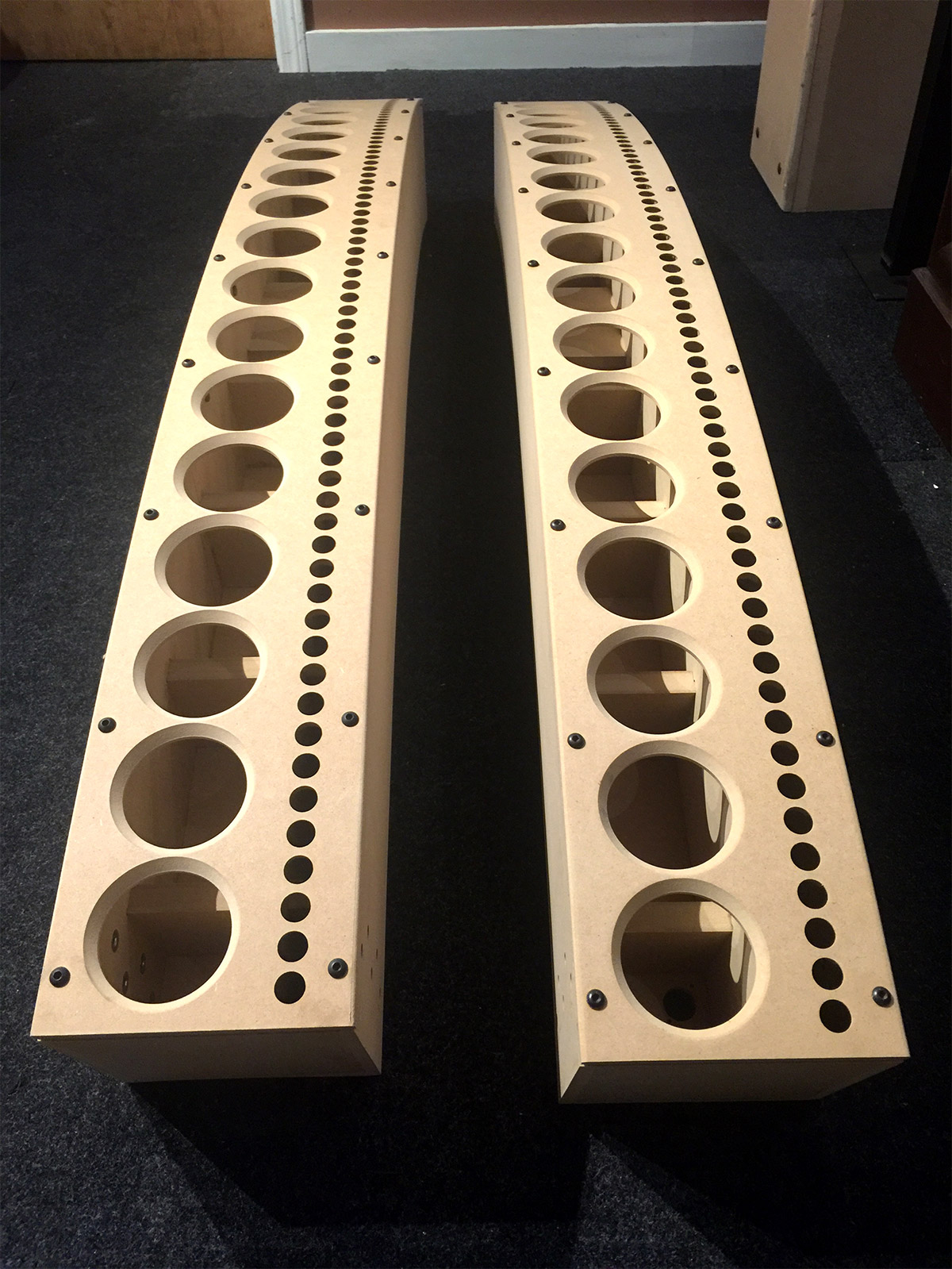
The CBT36 cabinets are shipped in three boxes. Two contain the MDF cabinets. The third contains the drivers, electronics, hardware, and manual. The manual is a 80+ page book of instructions with lots of images that accompany step-by-step instructions. My kind of manual! The first thing the manual tells people to do is an inventory check. There are hundreds of components (screws, wires, resistors, circuitry, and speaker drivers) to inventory and check.
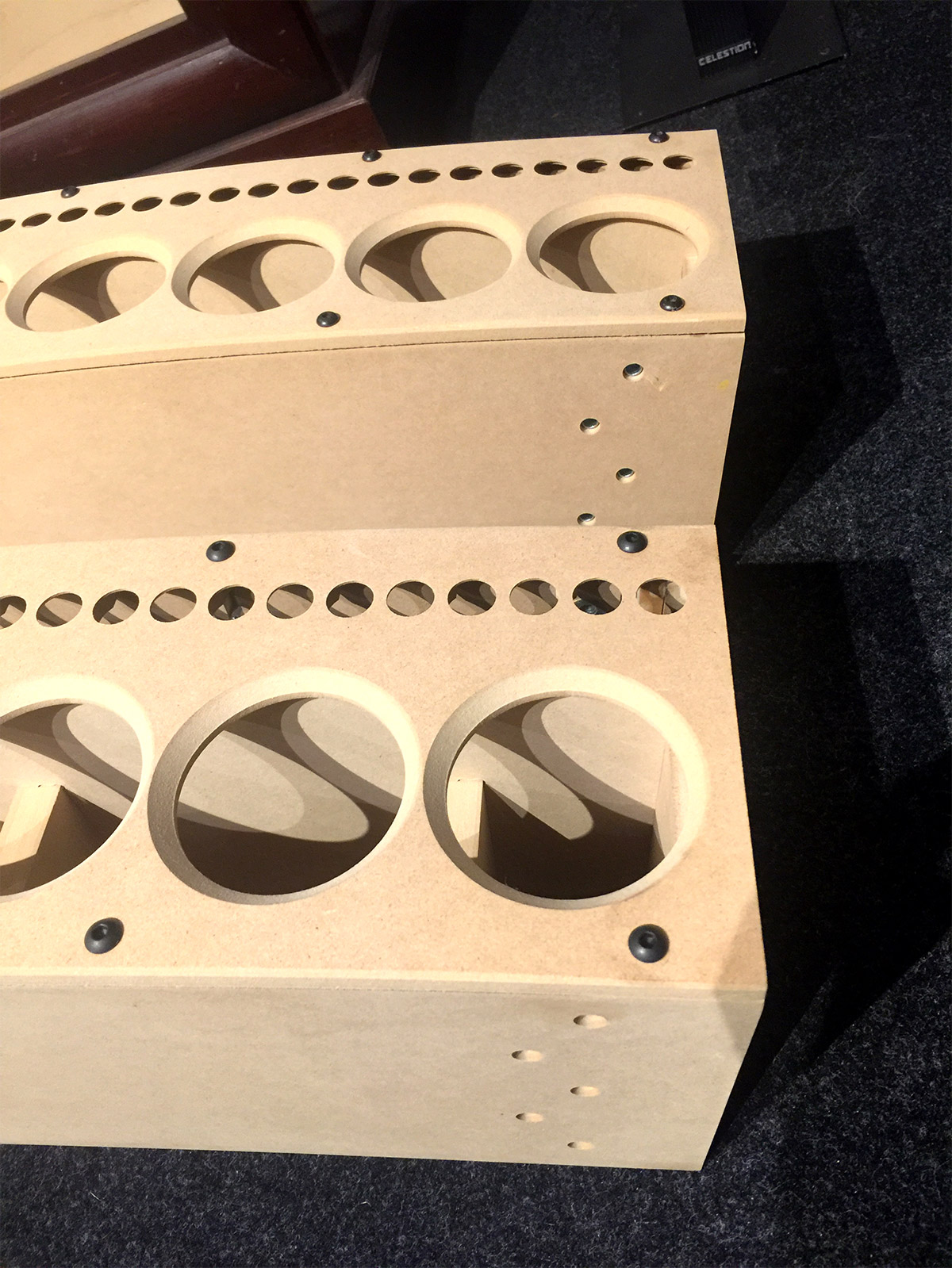
Some of the components require testing, and this is the first step taken since replacement parts take time to ship. Testing everything is absolutely critical to a successful build. I ran into a few issues with some of the speaker drivers and had to get replacements for two full range drivers and a tweeter array. Additionally, I had to send the cabinets back. The manual tells people not to throw away the shipping boxes just in case this happens. See if you can spot the reason why I rejected these cabinets.
Veneering the front panels
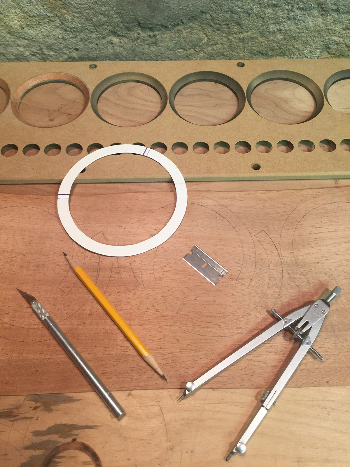
There are way too many steps in the build process to cover is a single post, so I am focusing primarily on the customization of the front panels. Some previous builders describe taking the panels to an auto body shop where they can be primed and coated with a glossy finish in a spray booth. That was not for me. I wanted the speakers to look like a piece of vintage furniture. I started with veneering the inner bevels for the main driver holes by producing a card template for cutting individual pieces from a thin sheet of adhesive mahogany veneer. No additional prep was needed for the front panels.
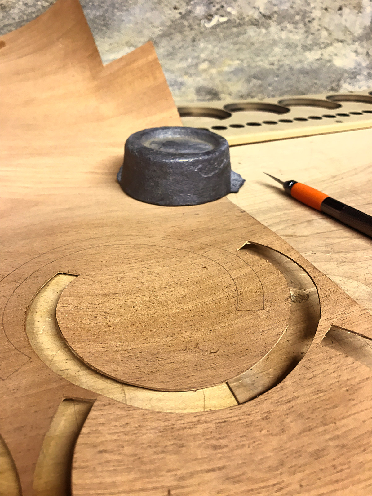
Here is a shot of a few of the cutouts and how I positioned them with the wood grain following the midpoint of each curve. I did this in anticipation of how the veneer would get trimmed in relation to the grain running down the face of the panels. I wanted a contrasting pattern that spread the light out differently on the beveled veneer.
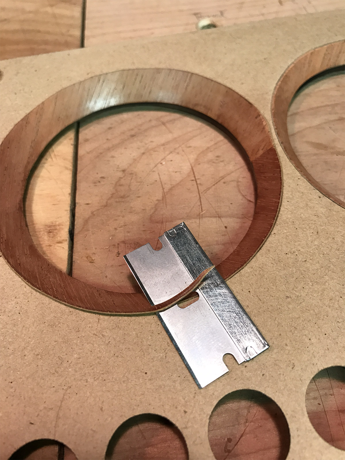
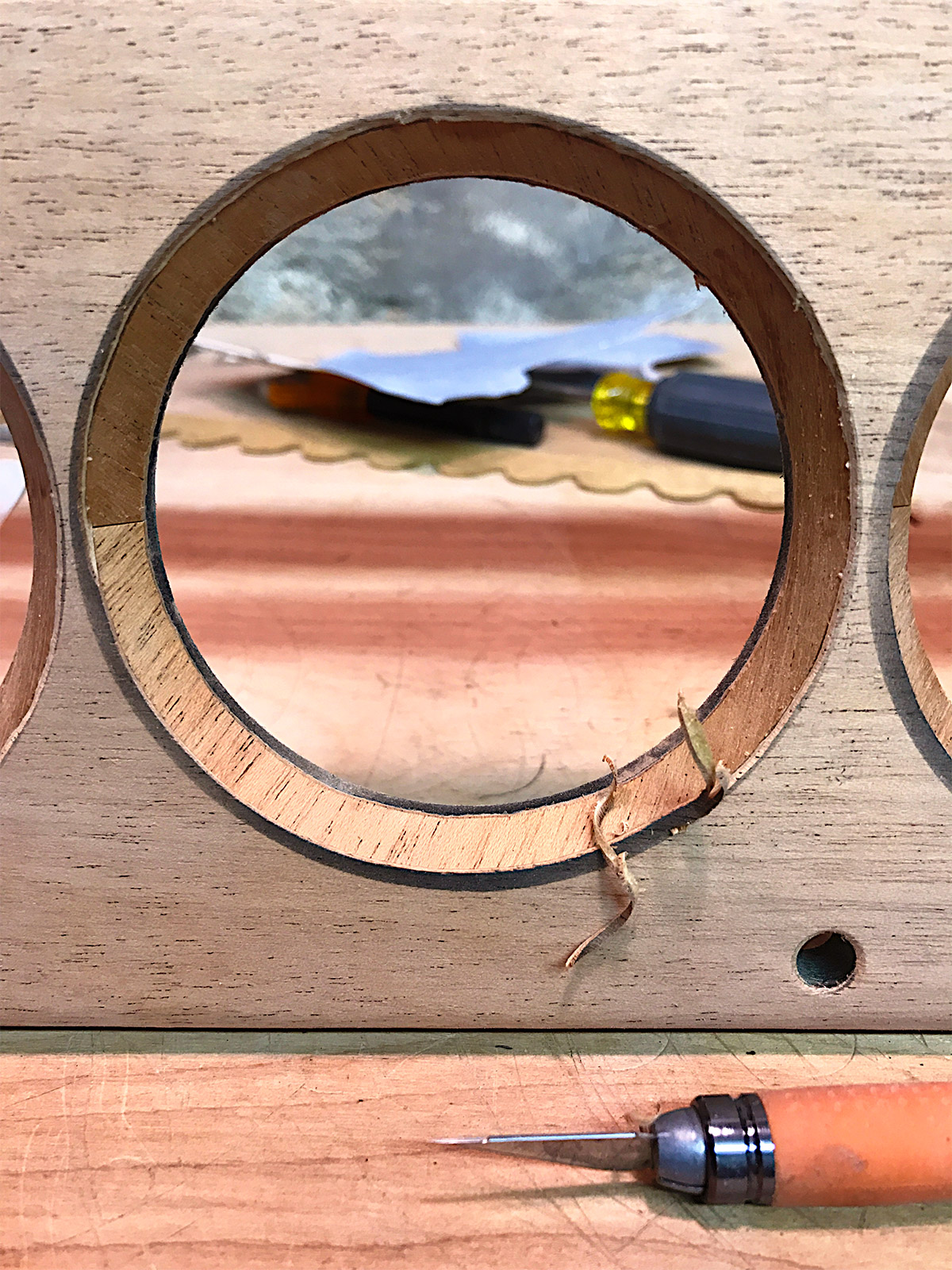
Here are some trimmed pieces of the veneer applied to the bevel in the panel. I did this with a soldering iron as a heat source and burnisher to fasten them really well before trimming. Then, I used a single edge razor blade as a trimming tool. The image shows the start of the trimming process on the top part of the bevel. I also trimmed The lower section of the bevel in the same fashion. one of the finished bevels can be seen in the upper right of the image.
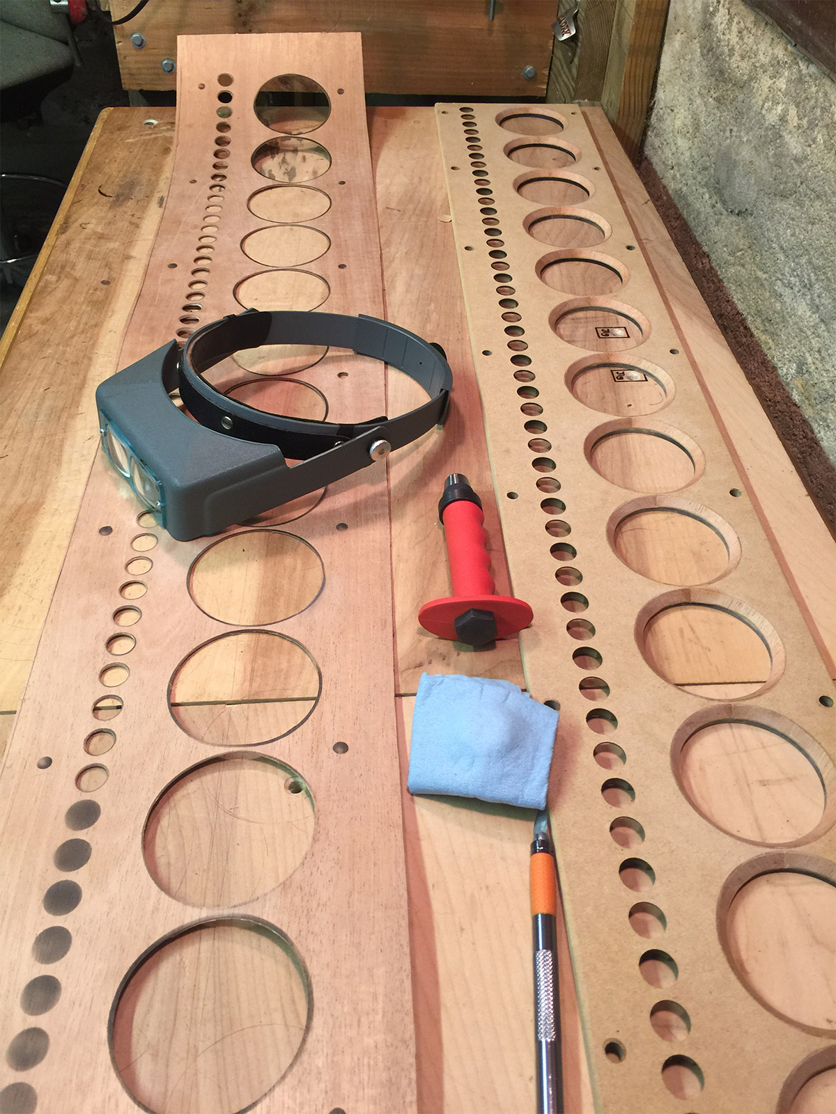
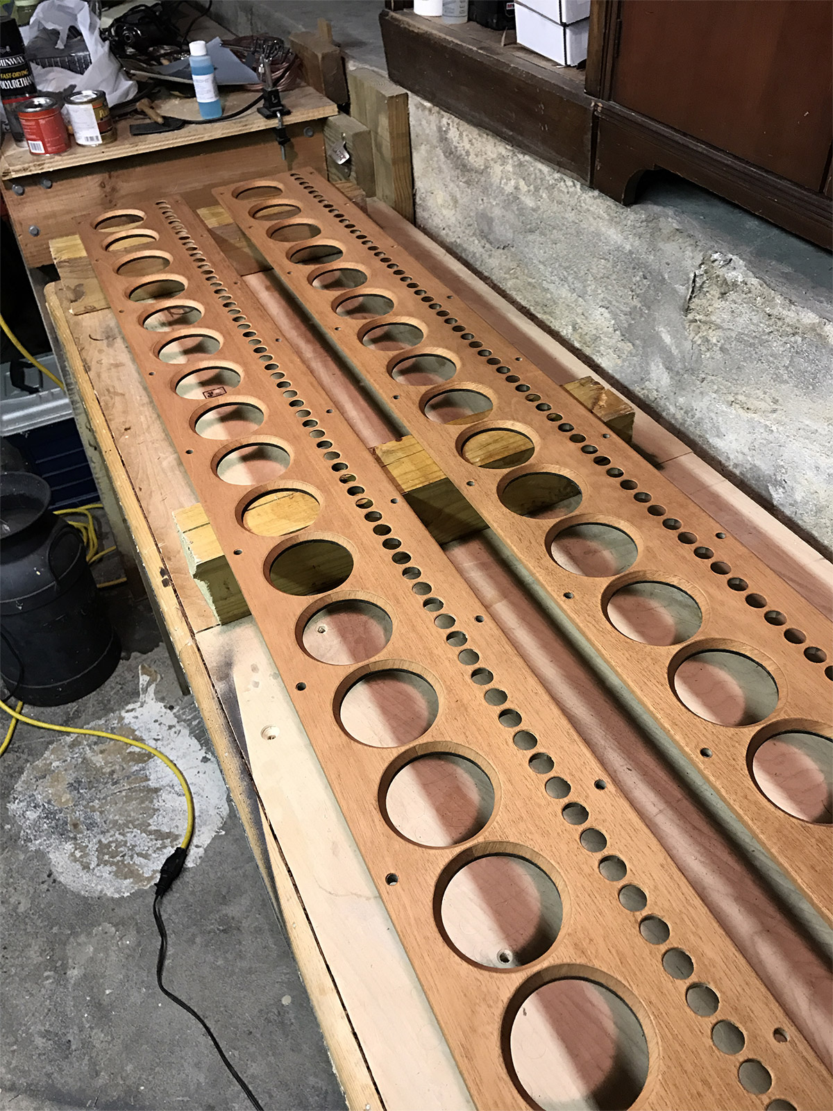
Prior to veneering the inner beveling of the main driver holes, I prepared longer sheets of the mahogany veneer by using an airbrush to spray markings for each cutout in the veneer. This image shows the final stage in the process of cutting. I used an Exacto knive for the larger holes and a leather punch for the smaller holes. The Optivisor helped me maintain the precision needed for the hand cutting process and positioning of the leather punch. Each cut left room for material to be removed after application.
With all rough cutting completed the front veneer is carefully positioned so that all the edges overlap each hole with additional veneer ready for precision trimming. I used a domestic iron to heat cure the veneer to the MDF, folding the edge of the veneer around the the camphor edges of the panel. Then I used an Exacto blade to do the final precision trimming.
Here I am using a rotary grinding bit to speed up the trimming process on the tweeter holes. There are 72 of these holes on each panel, so the grinder was essential for keeping the time spent on each hole down to about 5 minutes. Careful attention was taken not to enlarge the holes any more than the original MDF, which is about as thick as the vener in these areas.
The final stage in the veneering process was lots hand sanding! I used sanding blocks for the flat sections starting with 320 grit paper, working up to 600 grit. The beveled holes and tweeter holes required the same attention with small hand held sanding strips.
The trimming, application, and sanding process was repeated on the second panel, then I prepped both panels for a light stain with Minwax Pre-Stain and Minwax Old Maple to bring out the grain and the deeper reds in the mahogany. After a 24 hour drying stage I spent another 10 hours sanding to a polished finish with 1200 grit sand paper, then applying carnauba wax to seal the finish. The whole process took close to 150 hours.
Assembly
Here are the front panels flipped over on a felt lined workstation to protect the finish while mounting the drivers. I have just begun the wiring process at this stage. Most of the electronics assembly is covered in the manual, so I will just focus on some of the areas I deviated from the instructions to customize the look of the speakers, and enhance the build.
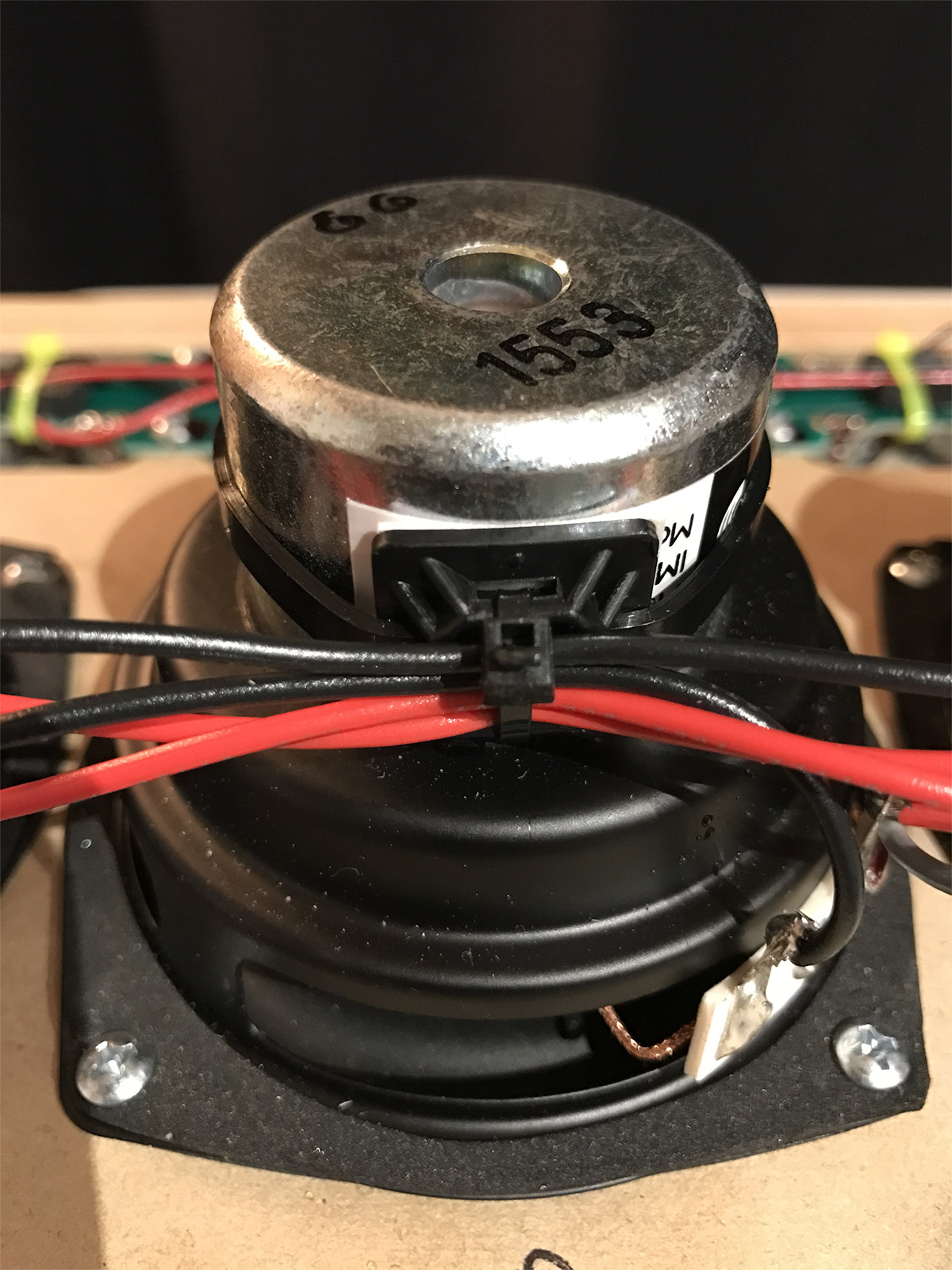
The manual had suggested mounting all the resistors with a hot glue gun, but I opted for a technique I read in the forums using zip ties. I also applied acoustic foam between each resistor and the mount to eliminate the possibility of any component causing vibration inside the cabinet.
I used the same technique to fasten bundles of wires down the length of the array for both the full range drivers and the tweeters.
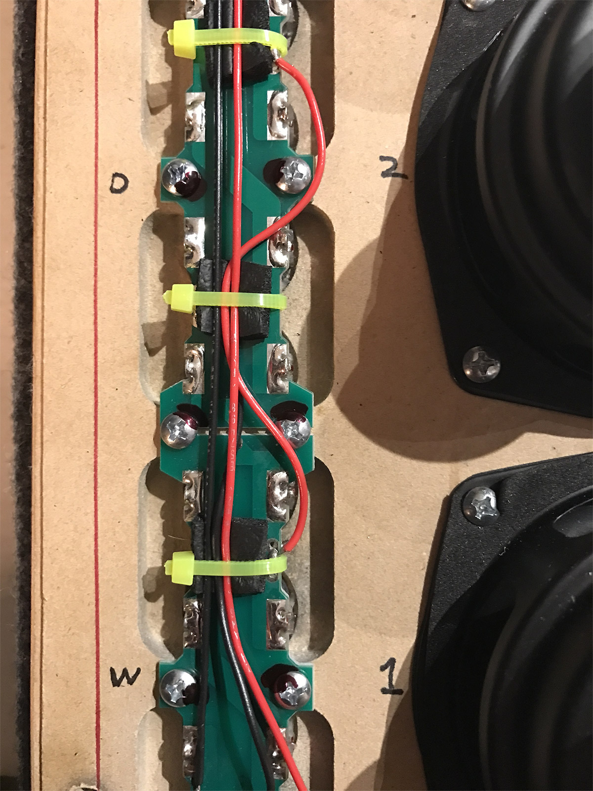
The same wire fastening technique is seen here. Tweeter arrays come attached to circuit boards with four tweeters per board. The boards are screwed into place and connected with jumpers and wires depending upon how the banks are shaded (see the manual for a complete description). The numbers on the panel mark positions for each set of drivers. Before mounting the drivers I tested and ranked the impedance of each one, placing speakers with a slightly lower impedance towards the top end of the speaker panel.
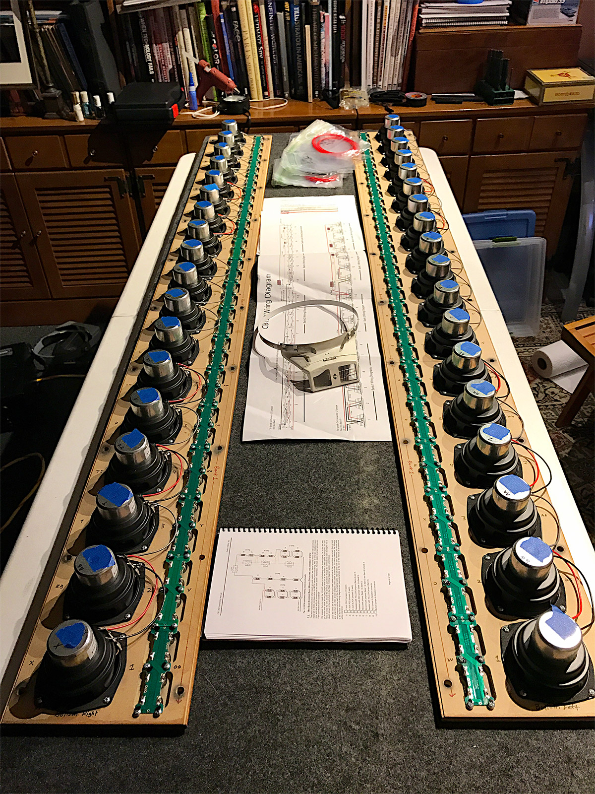
Here is the right panel fully wired for testing. I did testing twice since there is no margin for error once the wires and circuits are soldered into place. The first test confirmed all the drivers worked, and that the shading was correct. The second test confirmed the same results with the soldering complete.
This is the left panel undergoing the same testing prior to sealing the cabinets with a set of 20 wide flange brass bolts. The bolts are not part of the original parts list. I like the look of them better than the black ones that came with the kit. I opened and shut the cabinets a few times, which is why only some bolts are fastened in these images. The bolts have compressible rubber washers to seal the cabinet and protect the front panel.
